WP6-21: Difference between revisions
| (23 intermediate revisions by 2 users not shown) | |||
| Line 18: | Line 18: | ||
|- | |- | ||
| TRL || 3 | | TRL || 3 | ||
|- | |||
| Contact || fernando.herrera at acorde.com | |||
|} | |} | ||
| Line 24: | Line 26: | ||
It motivated the development of the '''IPS Modelling and Analysis Framework (IPS-MAF)''', which, as shown in the figure below, can be used from early design stages, to build up a holistic model of the IPS system. IPS-MAF can be used to analyse and decide key aspect at different levels of the indoor positioning system (deployment of the anchors, sensitivities and transmission powers, transmission frequencies, etc) while keeping a holistic view of the system. | It motivated the development of the '''IPS Modelling and Analysis Framework (IPS-MAF)''', which, as shown in the figure below, can be used from early design stages, to build up a holistic model of the IPS system. IPS-MAF can be used to analyse and decide key aspect at different levels of the indoor positioning system (deployment of the anchors, sensitivities and transmission powers, transmission frequencies, etc) while keeping a holistic view of the system. | ||
[[File:wp3- | [[File:wp3-15_1_04.png|frame|center|IPS-MAF provides a qualitative step towards a holistic, model-based design of Indoor Positioning Solutions for long infrastructures]] | ||
That is, IPS-MAF enables a holistic model of the IPS, while integrating some actual pieces of the application, so in that sense it also enables to advance some part of the application development. Therefore IPS-MAF feeds the conventional platform development and embedded application development phases, where ACORDE has already long expertise. At the same time, the measurements and characterizations that can be derived and refined from platform and application development serve to feedback and polish the holistic model. Summing up, an extended system-level design flow has been enabled, after coupling IPS-MAF to conventional ACORDE development processes for platform development (which includes PCB design, mechanical design, drivers’ development, embedded application development) and application development (where ACORDE typically develops in C or C++, relying on some cross-development environment suited to a specific microcontroller). | That is, IPS-MAF enables a holistic model of the IPS, while integrating some functional actual pieces of the application, so in that sense it also enables to advance some part of the application development. Therefore IPS-MAF feeds the conventional platform development and embedded application development phases, where ACORDE has already long expertise. At the same time, the measurements and characterizations that can be derived and refined from platform and application development serve to feedback and polish the holistic model. Summing up, an extended system-level design flow has been enabled, after coupling IPS-MAF to conventional ACORDE development processes for platform development (which includes PCB design, mechanical design, drivers’ development, embedded application development) and application development (where ACORDE typically develops in C or C++, relying on some cross-development environment suited to a specific microcontroller). | ||
== IPS-MAF Architecture == | == IPS-MAF Architecture == | ||
| Line 46: | Line 48: | ||
The analyses to be performed are also described in XML format. | The analyses to be performed are also described in XML format. | ||
[[File:C4D_WP6_IPS_MAF_A_xml_deploy.png | 500px |center| Most input information is passed to IPS-MAF in XML format (anchors deployment in the image)]] | |||
The IPS-MAF Analyzer parses all this input information and links the tag and anchor application models and performs the described analyses. | The IPS-MAF Analyzer parses all this input information and links the tag and anchor application models and performs the described analyses. | ||
| Line 53: | Line 57: | ||
<u>Dynamic analysis</u> refers to the possibility to perform a simulation and extract out of it different type of metrics, such as estimated positions of the tag and anchors, and errors with regard to their real position. | <u>Dynamic analysis</u> refers to the possibility to perform a simulation and extract out of it different type of metrics, such as estimated positions of the tag and anchors, and errors with regard to their real position. | ||
[[File:C4D_WP6_IPS_MAF_A_execution.png | 500px |center| Messages in console launched by IPS-MAF Analyzer]] | |||
Analysis configuration allows to select which specific outputs will be exported, in different formats (mostly, csv and KML for dynamic analysis). Some files are exported in other convenience formats (e.g., .pcd, png). All the outputs for a configured simulation are exported to an output folder, which can be controlled from the tool configuration too. | Analysis configuration allows to select which specific outputs will be exported, in different formats (mostly, csv and KML for dynamic analysis). Some files are exported in other convenience formats (e.g., .pcd, png). All the outputs for a configured simulation are exported to an output folder, which can be controlled from the tool configuration too. | ||
| Line 64: | Line 70: | ||
Following figures provide a | Following figures provide a | ||
Below, a sample of several types of visualizations which can be performed with the IPS-MAF Visualizer are shown. | Below, a sample of several types of visualizations of the static analysis outputs which can be performed with the IPS-MAF Visualizer are shown. | ||
<gallery> | <gallery widths=300px heights=200px > | ||
File: WP6_21_PDOP_analysis.png | PDOP analysis | File: WP6_21_PDOP_analysis.png | PDOP analysis | ||
File: WP6_21_HDOP_analysis.png | HDOP analysis | File: WP6_21_HDOP_analysis.png | HDOP analysis | ||
File: WP6_21_IPSMAF_obstacles.png | section visualization of PDOP analysis with obstacles in the tunnel | File: WP6_21_IPSMAF_obstacles.png | section visualization of PDOP analysis with obstacles in the tunnel | ||
File: WP6_21_path_analysis.png | Analysis on flight plan (histogram visualization behind) | | File: WP6_21_path_analysis.png | Analysis on flight plan (histogram visualization behind) | ||
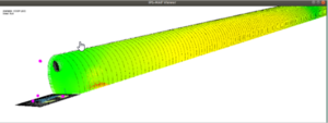
File: C4D_WP6_IPS_MAF_A_circle_section.png | HDOP analysis on a cicle section tunnel) | |||
File: WP6_21_IPS_MAF_obstacle_shadow.png | Shadows revealed in VDOP analysis) | |||
</gallery> | </gallery> | ||
| Line 77: | Line 85: | ||
IPS-MAF is related to the ACORDE IPS, and its development has been triggered and done in the frame of/thanks to COMP4DRONES. | IPS-MAF is related to the ACORDE IPS, and its development has been triggered and done in the frame of/thanks to COMP4DRONES. | ||
All the aforementioned features are supported with several demonstrative examples. | All the aforementioned features are supported with several demonstrative examples. | ||
It is remarkable that the outputs of the IPS-MAF simulations already served to detect issues when conventional least-squares algorithms were used, and to design and test the modified trilateration algorithm, even before the anchor or tag platforms were ready. IPS-MAF dynamic analysis revealed non-straightforward effects and outcomes as the one mentioned, difficult to advance with a manual analysis. | |||
Similarly, for the static analysis. For instance, notice the “coverage” pattern in depending the type of DOP (PDOP vs HDOP) and the “shadow” provoked at the floor by obstacles oh the roof of the tunnel. | |||
Some demo videos will be made available before the end of the project. | Some demo videos will be made available before the end of the project. | ||
Latest revision as of 16:22, 13 March 2023
Introduction
| ID | WP6-21 (WP6-IPS-MAF) |
| Contributor | ACORDE |
| Levels | Tool |
| Require | Linux (or Windows+WSL), Libraries: PCL, Xerces, GeographicLib, Matplotlib |
| Provide | Static and Dynamic (simulation based) of holistic model of Indoor Positioning System |
| Input | SystemC models of tag and anchor applications, XML-based description of the anchor deployment and other crucial parameters of the solution, of the configuration of the the analysis |
| Output | Static analysis outputs (Visibility, DOP, range for trcv configurations) and Dynamic analysis (accuracies, timing affected behaviour) |
| C4D tooling | System-Level modelling and analysis |
| TRL | 3 |
| Contact | fernando.herrera at acorde.com |
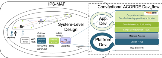
ACORDE IPS was motivated by the specific positioning needs and requirements for a drone flying on an large indoor scenario. The need for considering different requirements, several aspects and levels of a Cyber-physical system (tunnel geometry, deployment of anchors, algorithms for 3D positioning, platform limitations, interfaces) made early evident that a more holistic, model-based design was necessary. It motivated the development of the IPS Modelling and Analysis Framework (IPS-MAF), which, as shown in the figure below, can be used from early design stages, to build up a holistic model of the IPS system. IPS-MAF can be used to analyse and decide key aspect at different levels of the indoor positioning system (deployment of the anchors, sensitivities and transmission powers, transmission frequencies, etc) while keeping a holistic view of the system.
That is, IPS-MAF enables a holistic model of the IPS, while integrating some functional actual pieces of the application, so in that sense it also enables to advance some part of the application development. Therefore IPS-MAF feeds the conventional platform development and embedded application development phases, where ACORDE has already long expertise. At the same time, the measurements and characterizations that can be derived and refined from platform and application development serve to feedback and polish the holistic model. Summing up, an extended system-level design flow has been enabled, after coupling IPS-MAF to conventional ACORDE development processes for platform development (which includes PCB design, mechanical design, drivers’ development, embedded application development) and application development (where ACORDE typically develops in C or C++, relying on some cross-development environment suited to a specific microcontroller).
IPS-MAF Architecture
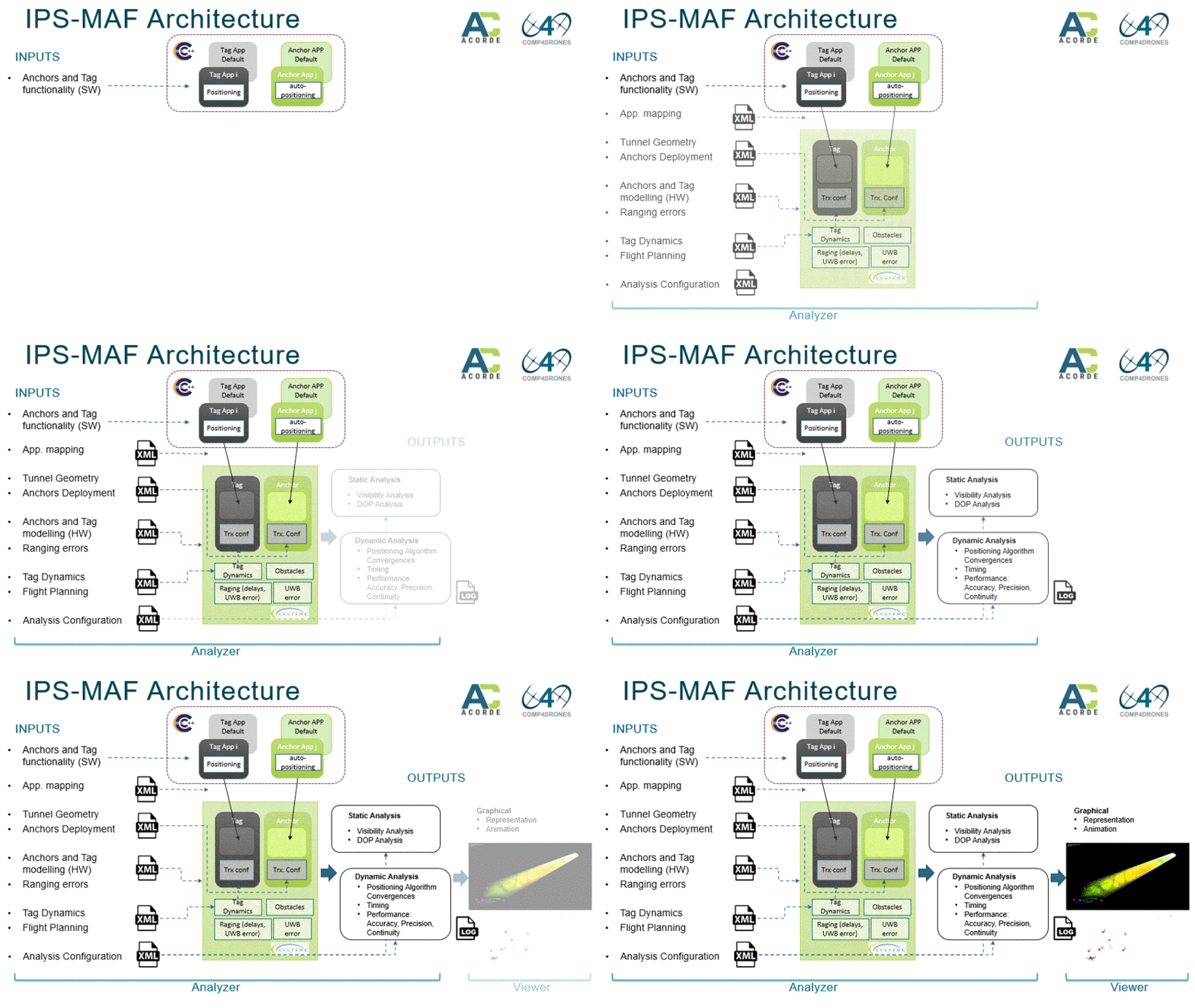
Following figure sketches the main architecture of IPS-MAF.
IPS-MAF is composed by two main tools:
- The IPS-MAF Analyzer
- The IPS-MAF Visualizer
IPS-MAF Analyzer
A main input to the IPS-MAF Analyzer is a model of the anchor and tag applications. They are developed separately from the IPS-MAF tool as SystemC models. This is convenient, as this description is very close to a final C/C++ implementation, while relying on a SystemC API enables a target independent and standard description. Different application models can be separately developed and compiled and (dynamically) linked to the IPS-MAF Analysis tool. Such mapping is described in XML format.
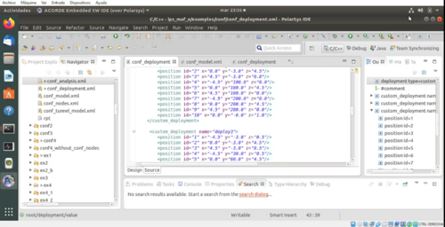
A set of XML files serves to specify such a mapping of tag and anchor applications, and other main aspects (anchors deployment, tunnel geometry, main HW parameters like UWB transceivers configuration, tag dynamics) of the IPS with large potential impact on performance.
The analyses to be performed are also described in XML format.
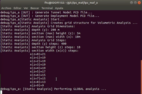
The IPS-MAF Analyzer parses all this input information and links the tag and anchor application models and performs the described analyses. Notice that, despite the dynamic, simulatio-based analysis relies on SystemC, none of the requested analysis requires any compilation. The IPS-MAF Analyizer can be seen (as is) a command line tool that reads some inputs and produce some outputs.
Static analysis comprise visibility of the anchors and Dilution of Precision (DOP) for any point of the infrastructure. It also comprises the analysis of the range (and in general, of the link margin) for different configuration of transmitting and receiver configurations.
Dynamic analysis refers to the possibility to perform a simulation and extract out of it different type of metrics, such as estimated positions of the tag and anchors, and errors with regard to their real position.
Analysis configuration allows to select which specific outputs will be exported, in different formats (mostly, csv and KML for dynamic analysis). Some files are exported in other convenience formats (e.g., .pcd, png). All the outputs for a configured simulation are exported to an output folder, which can be controlled from the tool configuration too.
IPS-MAF Visualizer
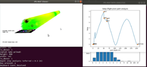
The IPS-MAF Visualizer is a graphical front-end that takes as input the outputs produced by the IPS-MAF analyzer and show a 3D visualization of them. It also uses some inputs to the IPS-MAF Analyzer (bypassed to the output folder), e.g. to visualize the tunnel model, anchors deployment, obstacles, flight plan.
The IPS-MAF Visualizer supports the visualization of both, outputs of the static analyses, and of the dynamic analyses. Following figures provide a
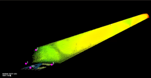
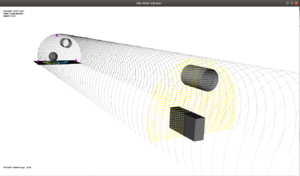
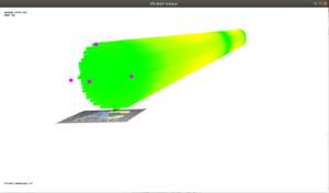
Below, a sample of several types of visualizations of the static analysis outputs which can be performed with the IPS-MAF Visualizer are shown.
Status after C4D
IPS-MAF is related to the ACORDE IPS, and its development has been triggered and done in the frame of/thanks to COMP4DRONES. All the aforementioned features are supported with several demonstrative examples.
It is remarkable that the outputs of the IPS-MAF simulations already served to detect issues when conventional least-squares algorithms were used, and to design and test the modified trilateration algorithm, even before the anchor or tag platforms were ready. IPS-MAF dynamic analysis revealed non-straightforward effects and outcomes as the one mentioned, difficult to advance with a manual analysis. Similarly, for the static analysis. For instance, notice the “coverage” pattern in depending the type of DOP (PDOP vs HDOP) and the “shadow” provoked at the floor by obstacles oh the roof of the tunnel.
Some demo videos will be made available before the end of the project.
