WP6-26: Difference between revisions
| (12 intermediate revisions by one other user not shown) | |||
| Line 1: | Line 1: | ||
== Introduction == | == Introduction == | ||
{|class="wikitable" | {|class="wikitable" | ||
| ID|| WP6- | | ID|| WP6-26 | ||
|- | |- | ||
| Contributor || UNICAN | | Contributor || UNICAN | ||
| Line 7: | Line 7: | ||
| Levels || Tool, Platform | | Levels || Tool, Platform | ||
|- | |- | ||
| Require || Linux | | Require || Linux Ubuntu 18.04 | ||
|- | |- | ||
| Provide || Timing/Energy | | Provide || Timing/Energy Simulation | ||
|- | |- | ||
| Input || | | Input || XML system description & functional code | ||
|- | |- | ||
| Output || Functional | | Output || Functional & performance simulation results | ||
|- | |- | ||
| C4D tooling || n.a. | | C4D tooling || n.a. | ||
|- | |- | ||
| TRL || | | TRL || 5 | ||
|- | |||
| Contact || evillar at teisa.unican.es | |||
|} | |} | ||
| Line 30: | Line 32: | ||
SoSIM covers the following states in the mechatronic V-Cycle of Figure 2: | SoSIM covers the following states in the mechatronic V-Cycle of Figure 2: | ||
[[File:wp6-26-D-01.png|frame|raight|Figure 2 - S3D-SoSIM V cycle coverage]] | |||
2. System Design | |||
3. Mechanical Analysis and Design | |||
4. IT Analysis and Design | |||
5. SW Analysis and Design | |||
6. HW Analysis and Design | |||
7. SW Detailed Design | |||
9. SW Component Verification | |||
10. SW Integration and Verification | |||
11. HW Integration and Verification | |||
12. Mechanic Integration and Verification | |||
13. IT Integration and Verification | |||
14. System Integration and Verification | |||
15. System Acceptance Verification | |||
The improvement provided by SoSIM comes from the fact that the use of virtual models of the system simplifies simulation-based DSE, which greatly reduces the time required to select the most appropriate solution [2]. However, as the information about the system and its components evolve along the design process, so should their models and, in general, the infrastructure required for their simulation. As a result, different simulation levels must be considered during the different steps of the design and verification process. Table 1 shows the four simulation levels considered for the functional components: | The improvement provided by SoSIM comes from the fact that the use of virtual models of the system simplifies simulation-based DSE, which greatly reduces the time required to select the most appropriate solution [2]. However, as the information about the system and its components evolve along the design process, so should their models and, in general, the infrastructure required for their simulation. As a result, different simulation levels must be considered during the different steps of the design and verification process. Table 1 shows the four simulation levels considered for the functional components: | ||
| Line 78: | Line 94: | ||
Regarding the simulation of the drones, four different models are considered. Let’s consider the command “move to X/Y/Z”. A minimal implementation will estimate the path and the movement time considering constant horizontal and vertical speed values, the power consumption, and will perform the movement in a single step (FN). In many cases, a more detailed model for the drone(s) is required. An autopilot and a physical simulator are needed. | Regarding the simulation of the drones, four different models are considered. Let’s consider the command “move to X/Y/Z”. A minimal implementation will estimate the path and the movement time considering constant horizontal and vertical speed values, the power consumption, and will perform the movement in a single step (FN). In many cases, a more detailed model for the drone(s) is required. An autopilot and a physical simulator are needed. | ||
In this case, the full code (FC/FD) will generate all the signals to the motors required by the physical simulator to reach the final destination, including the estimation of all the intermediate positions, the actual time to reach them, the corresponding power consumption, angles and orientations. | In this case, the full code (FC/FD) will generate all the signals to the motors required by the physical simulator to reach the final destination, including the estimation of all the intermediate positions, the actual time to reach them, the corresponding power consumption, angles and orientations. | ||
| Line 120: | Line 135: | ||
[[File:wp6-26_IO_01.png|frame|center| Figure 3 - Interoperability of SoSim with other tools]] | [[File:wp6-26_IO_01.png|frame|center| Figure 3 - Interoperability of SoSim with other tools]] | ||
== References == | ==References== | ||
[1] J . Merino, R. Gomez, H. Posadas & E. Villar: "Multilevel host-compiled simulation framework for ROS-based UAV services using ArduCopter", proc. of the XXXVI Conference on Design of Circuits and Integrated Systems (DCIS), IEEE, 2021. | [1] J . Merino, R. Gomez, H. Posadas & E. Villar: "Multilevel host-compiled simulation framework for ROS-based UAV services using ArduCopter", proc. of the XXXVI Conference on Design of Circuits and Integrated Systems (DCIS), IEEE, 2021. | ||
Latest revision as of 08:49, 10 March 2023
Introduction
| ID | WP6-26 |
| Contributor | UNICAN |
| Levels | Tool, Platform |
| Require | Linux Ubuntu 18.04 |
| Provide | Timing/Energy Simulation |
| Input | XML system description & functional code |
| Output | Functional & performance simulation results |
| C4D tooling | n.a. |
| TRL | 5 |
| Contact | evillar at teisa.unican.es |
SoSIM is a new System-of-Systems Simulation tool developed in Comp4Drones. Its background technology is VIPPE. From the Single-Source System Design (S3D) model, the specific information required to perform a certain simulation and performance analysis task (e.g. performance simulation of a solution in a design-space exploration) is extracted and the corresponding simulation model, synthesized. This Model-to-Model generation is performed by the mSSYN tool.
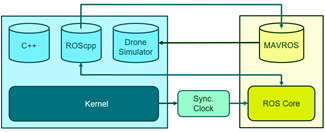
In order to extend SoSIM to mechatronic systems, several improvements have been carried out. The basic infrastructure allowing to simulate multiple drones and combining different levels for the different system components including ROS was described in [1]. The architecture of the complete simulation environment is shown in Figure 1. The arrows represent the control flow in the simulator. Depending on the simulation level, some of the functional blocks may be inactive. So, at the functional level ROS is not used. Thus, neither the ROS core and the MAVROS block, nor the Sync.Clock ROS node are required. The functional drone simulator (now to be extended to several drones) interacts directly with the ROScpp components. This is kept even when the ROS core is included. The synchronization clock will also be needed. Only when any of the drones is modeled with a detailed autopilot and physics, the MAVROS block is added in order to support the communication with the drone through MAVLink.
Detailed Description
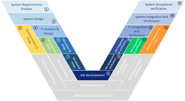
SoSIM covers the following states in the mechatronic V-Cycle of Figure 2:
2. System Design
3. Mechanical Analysis and Design
4. IT Analysis and Design
5. SW Analysis and Design
6. HW Analysis and Design
7. SW Detailed Design
9. SW Component Verification
10. SW Integration and Verification
11. HW Integration and Verification
12. Mechanic Integration and Verification
13. IT Integration and Verification
14. System Integration and Verification
15. System Acceptance Verification
The improvement provided by SoSIM comes from the fact that the use of virtual models of the system simplifies simulation-based DSE, which greatly reduces the time required to select the most appropriate solution [2]. However, as the information about the system and its components evolve along the design process, so should their models and, in general, the infrastructure required for their simulation. As a result, different simulation levels must be considered during the different steps of the design and verification process. Table 1 shows the four simulation levels considered for the functional components:
| Level | Code | Timing/Energy | ROS MW |
|---|---|---|---|
| MN | minimal | no | yes/no |
| MC | minimal | constant | |
| FC | full code | constant | |
| FD | full code | data dependent |
In MN (minimal/no), no model of time/energy is provided so that the code is supposed to be executed infinitely fast and without consuming any energy. In MC (minimal/constant) and FC (functional/constant), a constant time/energy is assumed each time the function is executed. These can be estimated or observed worst-case, mean-case or best case figures. In FC, the simulation time would be higher than in MC, as the actual code is executed. In the FD (functional/data dependent) model, both time and energy must be estimated over the actual code, using a state of the art technique, such as native simulation technology or binary translation.
Additionally, not all the system components need to have the same level of detail in a single simulation. Different system components can require simulation at different abstraction levels, resulting in heterogeneous simulations, depending on the focus of each simulation. For example, components under development usually require the most accurate simulation level (FD) when verifying their correctness while library components may only require FC simulation.
This multi-level capability is also applicable to the simulation infrastructure. For example, in robotic-based systems considered in this paper, at any of these levels it should be possible to include in the simulation the ROS infrastructure or not. The latter case would allow designers to focus on the functionality of the distributed, heterogeneous functionality. Once this is verified, the former would include the actual ROS infrastructure in order to confirm that the application functionality behaves correctly when the actual communication middleware (MW) is included.
Regarding the simulation of the drones, four different models are considered. Let’s consider the command “move to X/Y/Z”. A minimal implementation will estimate the path and the movement time considering constant horizontal and vertical speed values, the power consumption, and will perform the movement in a single step (FN). In many cases, a more detailed model for the drone(s) is required. An autopilot and a physical simulator are needed.
In this case, the full code (FC/FD) will generate all the signals to the motors required by the physical simulator to reach the final destination, including the estimation of all the intermediate positions, the actual time to reach them, the corresponding power consumption, angles and orientations.
However, these two abstraction levels can be not enough for certain components. As commented above, S3D is based on a service-provided communication paradigm. However, ROS is mostly based on a client/subscriber approach. Thus, an approach based on services that performs the required operation in a single step, such as the one proposed above for the drone model, is not adequate, since publishers typically require a continuous flow of data. To solve this, and considering that the drone model is the most critical element in the simulation of drone-based systems, this work proposes a third, intermediate abstraction level for this component, capable of providing intermediate values to be published. Following the previous example, the command “move to X/Y/Z” will result in a continuous flow of approximate positions and orientations to be published. As a summary, the proposed drone model levels proposed are those shown in Table 2:
| Level | Drones modeling | ROS MW |
|---|---|---|
| FY/FN | Functional | yes/no |
| AP | Autopilot | yes |
| MP | Multi-Physics | yes |
The simulation framework should support mixing functional and detailed simulation models for the drones in a multi-drone service. It should enable the system engineer to decide the best combination of abstraction levels in Tables 1 and 2. Supporting multi-level simulation requires that each component in the functional architecture is associated with models at several abstraction levels, each involving different accuracy/speed ratios.
Finally, it is mandatory to consider that drone based-systems usually involve multiple drones, and these drones can even require different simulation levels, in order to achieve high accuracy in some of the drone models while maintaining enough speed for the whole simulation.
The new verification tasks introduced in the V-Cycle of Figure 2 are the following:
- Validation: The goal of the System Design, Mechanical Analysis and Design, IT Analysis and Design, SW Analysis and Design, HW Analysis and Design and SW Detailed Design is to ensure that the hierarchical partitioning of the system in sub-systems and finally, mechanical and HW and SW components, keeps the functional and non-functional requirements stated at the beginning of the design process. As the domain restrictions such as inputs, outputs, rates and throughputs are usually defined in the system requirements analysis steps, the full test-bench can be developed. The test-benches developed at the system, subsystem and component levels during design validation can be reused for component, sub-system and final system verification. The system-level test-bench can be also largely re-used for DSE and HW/SW co-design. The test-benches may also help during component, sub-system and system testing when the test-bench or part of it is emulated via SW-in-the-Loop (SIL). In order to be able to verify the test-bench at such a high level, a minimal functionality implementing the fundamental features of the system, subsystems and/or the components in the final full system architecture, should be developed (MN). This initial code can also be combined with preliminary, predefined time/energy figures in order to enable a first performance analysis of the system (MC). Regarding the drone(s), a functional model (FN) is the most appropriate. This functional simulation is useful during system requirement analysis and system architectural design and partitioning. After this initial stage, the components to be reused are selected and the components to be developed from scratch are fully specified so that their development (i.e. programming) can start, in case of HW/SW components. In the case of robots (i.e. the drones), their modelling, simulation and design can start. Reusability does not affect only application components but also components in the test-bench (e.g. the drones in the context of this paper).
- Verification: Once the complete code has been developed, SW Component Verification, SW Integration and Verification, HW Integration and Verification, IT Integration and Verification, Mechanic Integration and Verification and System Integration and Verification can be performed. By verification, functional and non-functional verification is meant. Simulating the full code allows functional verification and debugging. Performance analysis enables non-functional verification. Any error detected, would require code optimization, platform re-configuration, platform re-design or even, a new architectural mapping of functional components to HW resources. The advantage provided by the co-design approach is that these design decisions are made at the same stage and only in a few cases it is required to backtrack to a previous stage. Among the different valid solutions during this Design-Space Exploration (DSE), the most appropriate Pareto point is selected [3]. As drones are basically real-time systems, consideration of timing (and potentially, energy) is usually mandatory. However, timing analysis is not an easy and fast task. To solve it, two different levels are proposed. In the first one, the full code is simulated but annotated with constant figures for the time/energy it consumes (FC). In a second level, once the component is mapped to a computing resource, native simulation is used so that accurate figures for execution times and energy can be obtained (FD). Although this is not covered in the paper, more detailed models for the SW can be used as virtualization or even an ISS. These simulation technologies may provide higher accuracy than native simulation at a lower simulation speed. These verification steps finish when the virtual model is accepted in the System Acceptance Verification stage so that its implementation can start.
- Testing is the new name we give to the former “HW-in-the-loop” verification steps as they require a physical prototype of the components, sub-systems and, finally, the complete system. Those components with potential reusability will be stored in the ‘Library of Components’.
Once the system is fully designed and accepted, the system can be produced and deployed in the field. Now, the system operation can be monitored and analysed so that it is possible to facilitate maintenance, reduce faults and minimize correction time, when needed.
Interoperability with other C4D tools
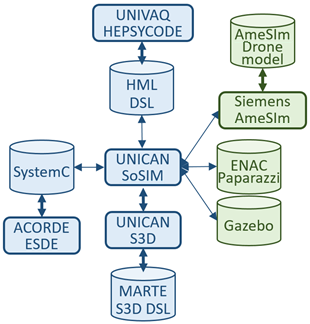
From the S3D model, the Model to Model (M2M) tool mSSYN generates the simulation model to be executed by SoSIM. As S3D may contain models from other simulators, so S3D is linked to them. Figure 3 describes the interoperability between SoSim and other simulators:
References
[1] J . Merino, R. Gomez, H. Posadas & E. Villar: "Multilevel host-compiled simulation framework for ROS-based UAV services using ArduCopter", proc. of the XXXVI Conference on Design of Circuits and Integrated Systems (DCIS), IEEE, 2021.
[2] F. Herrera, J. Medina, E. Villar: "Modeling Hardware/Software Embedded Systems with UML/MARTE: A Single-Source Design approach", in S. Ha and J. Teich (Eds): "Handbook of Hardware/Software Codesign", Springer. 2017.
[3] F. Herrera, H. Posadas, P. Peñil, E. Villar, F. Ferrero, R. Valencia and G. Palermo. “The COMPLEX methodology for UML/MARTE Modeling and design space exploration of embedded systems”, Journal of Systems Architecture, V.60, I.1, 2014.


