WP3-14 2: Difference between revisions
| (3 intermediate revisions by the same user not shown) | |||
| Line 24: | Line 24: | ||
|- | |- | ||
| TRL || 4 | | TRL || 4 | ||
|- | |||
| Contact || patrick.coirault at univ-poitiers.fr | |||
|} | |} | ||
| Line 85: | Line 87: | ||
[[File:wp3-14_2_03_2.png|frame|center|Communication topology]] | [[File:wp3-14_2_03_2.png|frame|center|Communication topology]] | ||
[[File:wp3- | [[File:wp3-14_2_03_3.png|frame|center|Formation tracking with stationary leader, distances in meters]] | ||
[[File:wp3- | [[File:wp3-14_2_04_2.png|frame|center|Formation tracking with a moving leader, distances in meters]] | ||
Siemens Simcenter AMESIM tool is also used to test the designed formation tracking scheme in more realistic environment. Following results is showing formation tracking of a follower with position offset as f_x=1m,f_y=-2m,f_z=0m. | Siemens Simcenter AMESIM tool is also used to test the designed formation tracking scheme in more realistic environment. Following results is showing formation tracking of a follower with position offset as f_x=1m,f_y=-2m,f_z=0m. | ||
[[File:wp3- | [[File:wp3-14_2_05_2.png|frame|center|Formation tracking simulation in AMESIM]] | ||
==Reference== | ==Reference== | ||
[1] Ajwad, Syed Ali, Emmanuel Moulay, Michael Defoort, Tomas Menard, and Patrick Coirault. [https://hal.archives-ouvertes.fr/hal-02508376/file/CDC19.pdf Distributed time-varying formation tracking of multi-quadrotor systems with partial aperiodic sampled data.] Nonlinear Dynamics (2022): 1-16. | [1] Ajwad, Syed Ali, Emmanuel Moulay, Michael Defoort, Tomas Menard, and Patrick Coirault. [https://hal.archives-ouvertes.fr/hal-02508376/file/CDC19.pdf Distributed time-varying formation tracking of multi-quadrotor systems with partial aperiodic sampled data.] Nonlinear Dynamics (2022): 1-16. | ||
Latest revision as of 08:31, 10 March 2023
Distributed control of multi-drone system
| ID | WP3-14_2 |
| Contributor | ENSMA |
| Levels | Function |
| Require | Communication service to obtain data from the neighbours |
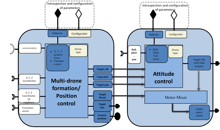
| Provide | Control algorithm for swarm formation control and cooperation, Inter-agent collision avoidance, Obstacle detection and avoidance, as well as mathematical stability proof of formation tracking |
| Input |
|
| Output | Required roll and pitch angles and thrust if used standalone, or rotors’ speed if used jointly with the attitude controller |
| C4D building block | Flight guidance if standalone, both Flight guidance and Flight control if used jointly with the attitude controller |
| TRL | 4 |
| Contact | patrick.coirault at univ-poitiers.fr |
Detailed Description
The effectiveness of the drones can be further improved by utilizing them in a cooperative manner to accomplish much more complex tasks which cannot be realized by solo operation. Control of such cooperative teamwork of Multi-Agent Systems (MAS) heavily depends on communication and information exchange among the agents. This gives rise to two natural choices of communication network which are centralized and distributed control network. In centralized communication, as apparent from the name, there is a central unit to which all the agents are connected to and send their information. The central station handles all the information exchange and sends control commands to the agents. This kind of scheme has some major drawbacks. For example, if the central unit fails, the whole network will collapse. Moreover, a centralized control scheme cannot handle large number of agents due to network saturation and/or limited computing and processing capability etc. On the other hand, a distributed control scheme does not require a central control unit. Agents communicate directly with their neighboring agents and exchange information. The information received from neighbors is also called local information. Each agent in the distributed network uses this local information to compute its own control input. Distributed control schemes offer many advantages over the centralized control scheme in terms of efficiency, adaptability, robustness, and scalability.
In many practical scenarios, it is required that the agents of MAS create and maintain a desired geometric shape. The required shape could either be fixed or time varying. In some cases, it is further required that the agents follow a trajectory while maintaining the shape. The reference trajectory is produced by a virtual or real leader. This is known as formation tracking.
Contribution and Improvements
The main goal of this enabling technology is to offer a distributed formation tracking controller for a swarm of drones. From the state of art, it is clear that the available cooperative control schemes do not take various practical limitations in-to account. Motivated by this, we focused on the design and implementation of distributed cooperative control laws for a swarm of drones with communication and sensor constraints described below in details. * Generally, formation controller requires both position and velocity of the neighbors for its computation. However, it is not always possible to measure all the states in real applications. Moreover, sending partial information consumes less bandwidth and thus is very cost effective. Therefore, it is considered that only position information is shared between the agents. We consider that velocity and control input of neighbors are not available.
- The data is transmitted between the agents at irregular and asynchronous time instants. Here, asynchronous means that the time of the transmission of the position data by one agent does not depend on any other agent in the network. In other words, an agent can receive information from its neighbors at different time instants. In fact, having irregular and asynchronous time periods in any practical case is totally inevitable.
- Another constraint that is considered is that the communication between the agents could either be directed or undirected. Directed communication means that if agent i can receive information from agent j then it does not imply that agent j can receive information from agent i.
- • Only a few agents in the network have the access to the reference trajectory produced by the virtual or real leader
Since inter-agent collision is another important issue in formation tracking control, a potential function based collision avoidance algorithm is incorporated with the proposed formation tracking controller. The collision avoidance algorithm ensures that the drones converge to produce the desired geometric shape without colliding with each other. The desired geometric shape can be defined by a formation vector.
Quadrotor mathematical model
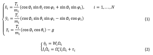
Quadrotors are not only inherently nonlinear but also under-actuated systems. The overall quadrotor system is under-actuated since there are four control inputs (four motor speeds) and six outputs (x, y and z position and roll (∅) pitch (θ) and yaw (φ) angles). The position dynamics for quadrotor “i” in a network is given by (1) while attitude dynamics are given by (2)
where T_i and m_i are the total thrust and mass of quadrotor “i” while Ω_i=〖[ω_(i,1) ω_(i,2) ω_(i,3) ]〗^T, I_i=diag{I_(i,1),I_(i,2),I_(i,3) }, τ_i=〖[τ_(∅_i ) τ_(θ_i ) τ_(φ_i ) ]〗^T and
formation geometry
The desired formation pattern can be defined by a formation vector F(t)=[f_1 (t)^T.... f_N (t)^T ] where f_i (t)=[f_(i,ξ)^T,f_(i,v)^T ] satisfies f ̇_(i,ξ)=f_(i,v).
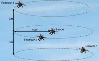
f_(i,ξ) and f_(i,v) are the corresponding position and velocity offsets of quadrotor “i” with respect to the reference trajectory. To further explain the notation of formation vector f_i (t) let us consider a network of quadrotors with a leader and three followers. Let the formation vector be chosen as
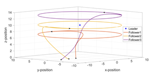
for i=1,2,3. This formation vector defines that the followers move around the leader in a circle of radius 10m with a phase difference of 2π/3. The altitude position offsets are constant with values -3m, 0m and 3m for follower 1, 2 and 3 respectively. A visual illustration of this formation is provided in the following figure.
Controller design and Implementation
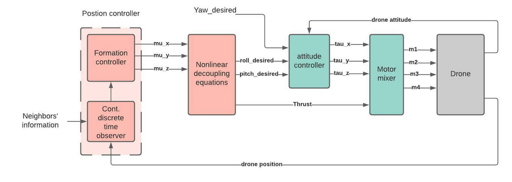
Since the drone is an under-actuated system (e.g. quadrotor has 6 states and 4 controllable rotor speeds), the design of controller is not straightforward. To achieve the desired formation of a swarm of drones, the overall dynamics of the drone is divided into two blocks namely position dynamics and attitude dynamics with a strong nonlinear coupling among them. The idea is to introduce an auxiliary position controller μ=[μ_x;μ_y;μ_z ]^Tand design it while keeping all the above mentioned constraints in mind. The required thrust and attitude then can be computed through this auxiliary position controller. An attitude controller then can be designed to achieve the required attitude by the drone and which makes the drone to reach to the required position to achieve the desired formation shape. Figure 2 shows the block diagram of the overall control architecture of one drone to achieve formation tracking of the swarm of drones. The position controller computes auxiliary position controller μ which is then used to compute desired roll and pitch through nonlinear decoupling equations. These desired roll and pitch angles act as a reference input to the attitude controller which computes the required torques to track these desired angles.
Formation controller: The basic idea is to use a classical continuous linear consensus controller for MAS of second order dynamics. By introducing the auxiliary controller, the position dynamics can be represented as double integrator. However, trivial formation controller requires both position and velocity in continuous time. A continuous-discrete-time high-gain observer is used to compute both position and velocity from available discrete position data.
Each follower has a local observer which not only estimates the agent’s own states but also the states of its neighbors. The structure of the proposed observer-based formation tracking algorithm also has some advantages when it comes to communication delays and data packet dropouts. As each controller is using the estimated states provided by the local observer, by time stamping the measured position data, the estimation can be provided as soon as the data is received, even with a delay, by compensating it through increasing the computation speed of the observer. Moreover, if the information packet is lost during communication, the observer could still provide an estimation.
Attitude controller: The desired attitude and thrust is computed through the auxiliary controller and then a finite-time attitude controller is used to compute the required torques to achieve this desired attitude. These required thrust and torques are then fed to the motor mixer which generate the motor speed commands for all four motors which are required for the quadrotor desired motion.
The stability of the proposed controller is proved through rigorous mathematical analysis and the results have been published in [1].
Simulations
The designed control algorithm is verified using MATLAB simulation. Communication topology (see Figure) is used to the MATLAB simulation purpose where 0 represents the leader. The results of formation tracking are shown on the next figure. In the first scenario, the leader is hovering at the altitude of 10m while the followers start from their initial position and make the required formation. In the second scenario, the leader is moving with some acceleration while the followers track the leader’s trajectory while keeping the desired formation.
Siemens Simcenter AMESIM tool is also used to test the designed formation tracking scheme in more realistic environment. Following results is showing formation tracking of a follower with position offset as f_x=1m,f_y=-2m,f_z=0m.
Reference
[1] Ajwad, Syed Ali, Emmanuel Moulay, Michael Defoort, Tomas Menard, and Patrick Coirault. Distributed time-varying formation tracking of multi-quadrotor systems with partial aperiodic sampled data. Nonlinear Dynamics (2022): 1-16.
