WP6-25
Introduction
| ID | WP6- |
| Contributor | UNICAN |
| Levels | Tool, Platform |
| Require | Linux, Eclipse EMF |
| Provide | Executable system level modeling, automated generation of embedded software, native execution based validation |
| Input | Platform model |
| Output | Code generation |
| C4D tooling | n.a. |
| TRL |
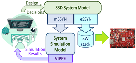
S3D (s3d.unican.es) is a model-driven, system design framework around a single UML/MARTE model [1]. The model is used as a centralized repository of all the information about the system which is relevant for the design. From the model, the specific information required to perform a certain simulation and performance analysis task (e.g. performance simulation of a solution in a design-space exploration) is extracted and the corresponding simulation model, synthesized. This Model-to-Model generation is performed by the mSSYN tool. The model is simulated by the VIPPE tool. It is worth mentioning that the M2M technology used to generate the simulation models automatically from the system model can be extended to synthesize the SW stack to be executed in each computational node. The corresponding synthesis tool is eSSYN (essyn.unican.es).
Contribution and Improvements
The fundamental S3D modeling methodology based on required-provided services has been extended in order to support components using ROS, a publish-subscribe communication middleware [2]. In this paper, Model-Driven Design (MDD) is proposed for modeling, simulation and performance analysis of SW intensive robot-based services. The work shows that robots can be integrated into a system engineering framework without affecting their modeling, design and development features. In order to seamlessly integrate these additional kinds of electro-mechanical components, a platform-based approach is proposed. The large number of different robots available makes it very difficult to reuse the same functional components from one project to another if the robots are changed. For certain kinds of robots with many similar functions, such as drones, a common list of methods can be defined so that the same code is valid for all of them simply by associating the functions with the appropriate code. An additional advantage of this common language is a significant reduction in the programming effort which can be reduced around 30%. The cost to be paid is a drop in simulation speed. In the use case of the paper, this reduction can be as high as 16% when a code intensive in ROS calls is used.
Another interesting result is that if the MDD modeling methodology is general enough, no extension is needed in order to support ROS. Identifying which components make use of ROS is sufficient. In this case, the ROS infrastructure is automatically integrated in the system and used by those ports requiring it. A methodology for rough estimation of execution time of the ROS code has been proposed. Although the error can be as high as 45%, the impact is small as the ROS code will be only a fraction of the total executable. In any case, an improvement over not annotating any execution time for ROS is achieved and this improvement is higher when it is more needed, that is, when the percentage of ROS code is higher. The improvement can be as high as 83.5% with only 2.55% of ROS code.
The proposed framework enables the seamless integration of robots into a MDD framework so that the whole service can be modelled, simulated and its performance analyzed, fully supporting essential stages of the V-Cycle as explained below.
Detailed Description
S3D covers the modelling and automatic generation of the multi-level executable models used to validate and verify the system at the different abstraction levels. S3D supports the modelling activities at each stage of the V-Cycle for mechatronic systems as explained below:
In all these stages, S3D supports reusability from previous projects as both functional and test-bench components can be imported from libraries:
- System Requirement Analysis. Based on Papyrus and the UML/MARTE standard, S3D can help in analysing and finally, specify the functional and non-functional requirements to be satisfied by the System (or System of Systems),
- System Design. Once the requirements have been specified, the system and its environment are fully specified in terms of the interface among them, the domain constraints (input rates, types and constraints among them) and the system functional and non-functional requirements (output rates, input/output delays, energy, etc.). As part of the System Design stage, partitioning of the system in the mechanical and the IT (digital) parts is performed. In S3D, the mechanical part will be incorporated to the Test-Bench (TB) of the (digital) system. As its functionality and performance is fully specified, the TB, including the model of the robots, can be developed.
- Mechanical Analysis and Design. The inclusion of the robots as TB components allows the analysis of their constraints and the design of the mechanical part (number and type of robots, design requirements to each one and among them, etc.).
- IT Analysis and Design. At this stage, the analysis and specification of the Platform-Description Model (PDM) can be performed. On the other side, the Platform-Independent Model can be specified.
- HW Analysis & Design. At this stage, the design of the initial Platform-Description Model (PDM), can be performed and an initial architecture of nodes and their internal HW architecture can be proposed. The final PDM will be decided later during architectural mapping as part of the System Integration & Verification stage.
- SW Analysis & Design and SW Detailed Design. During this stage, the hierarchical partitioning of the PIM in sub-systems and finally, components fully specified in their interfaces and functional and non-functional constraints, is decided.
- SW Development. The goal of this stage is to develop the code implementing the functional constraints. Papyrus supports both the Modelling and the Development Views and S3D links one with the other by annotating the components with their implementation files using the file’s paths as properties.
- SW Component Verification. S3D links each component with their Test-Benches so that the component can be verified both in the host (verification) and the target platform (testing) in case it has been decided already and it is available.
- In the rest of stages:
- SW Integration & Verification.
- HW Integration & Verification.
- IT Integration & Verification.
- Mechanical Integration & Verification.
- System Integration & Verification.
- System Acceptance Verification.
S3D helps in supporting the improvement of the model through the different stages and the automatic generation of the executables models so that the functional and non-functional constraints can be verified. Architectural mapping, that is, the final mapping of functional components in the PIM to execution resources in the PDM is fixed during System Integration and Verification when an accurate simulation and performance analysis model including the actual code can be generated. This model can provide accurate metrics ensuring final satisfaction of the implementation decided after Design-Space Exploration of as many possibilities as required.
Interoperability with other C4D tools
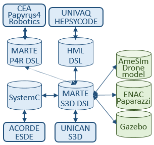
S3D is based on fundamental Model-Driven, Component-Based computational concepts. As a consequence, it keeps interoperability with many other system modeling environments. The following picture shows the interoperability of S3D with other tools in the C4D design and Verification environment:
References
[1] E. Villar, J. Merino, H. Posadas, R. Henia & L. Rioux: “Mega-modeling of complex, distributed, heterogeneous CPS systems”, Microprocessors and Microsystems, V.78, 2020.
[2] J. Merino, R. Gomez, H. Posadas and E. Villar: "Modeling and Performance Estimation of Robotic Systems using ROS: Application to drone-based Services," in proc. of the Forum on specification & Design Languages (FDL), IEEE, 2021.


